|
405 Documentation
9.0
|


|
|
405 Documentation
9.0
|
|
ME 405 Term Project Submission
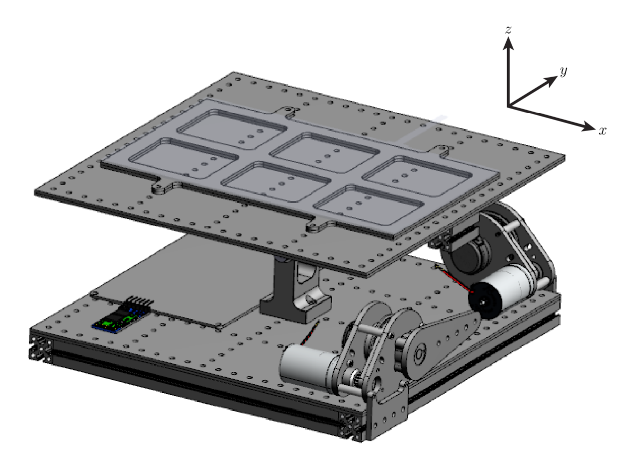
In this lab we finished development of our term project. The objective of the assignment was to balance a 2cm diameter rubber mouse ball on a two axis pivoting platform. The assembly consisted of the tilting platform, a resistive touch panel (ER-TP080-1) atop the platform, and two DC motors (controlled by a DRV8847 driver) on the assembly's base. The system was controlled by a Nucleo-L476RG flashed with MicroPython and connected to a custom PCB boot designed by Charlie Refvem of Cal Poly's Mechanical Engineering Department. The documentation for this lab is divided into the following sections:
The main lab file lab09_main.py successfully balances the platform. To operated it must be flashed onto the nucleo alogside its several. These files include: comboDriver.py, encoderDriver.py, motorDriver.py, and touchDriver.py. Additionally, the program uses the micropython, pyb, and utime libraries. The source code can be found on BitBucket (see Links)
To balance the ball its position and velocity must be found in addition to the angle and angular velocity of the platform. The position and linear velocity are determined using the resistive touch panel. The position is found by scanning the x and y-axes of the touch panel using the driver developed in Lab07 (touchDriver.py) Velocity is then determined by comparing the change in position of the ball between two readings with respect to time. The angle and angular position of the platform are measured using a similar method, but with the encoders rather than touch panel. Future iterations of this project will incorperate an IMU. Measurements from its integrated accelerometer compared with the known, vertical acceleration of gravity would provide the platform tilt angle. Meanwhile, the sensor's gyroscope would provide angular acceleration values.
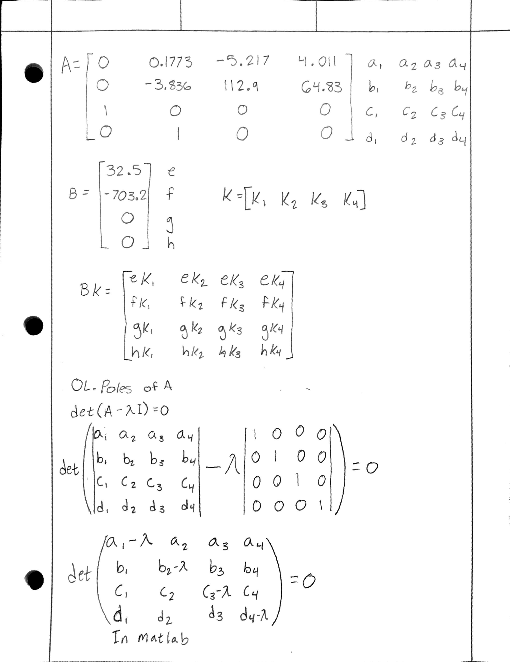
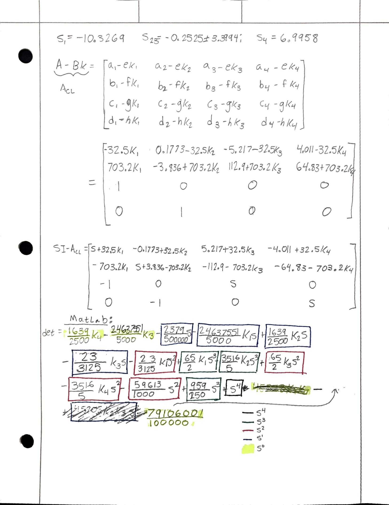
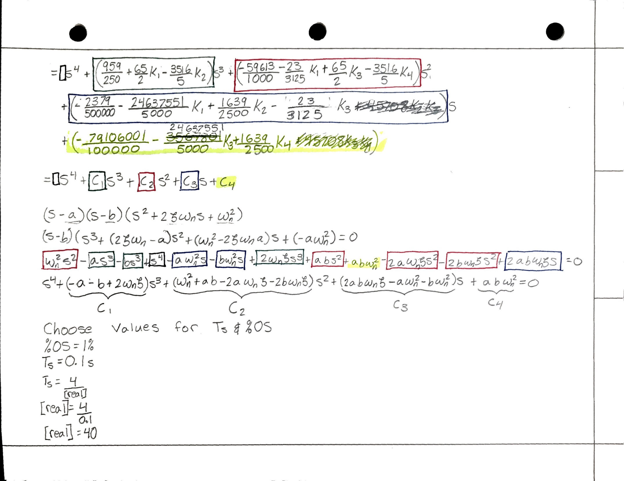
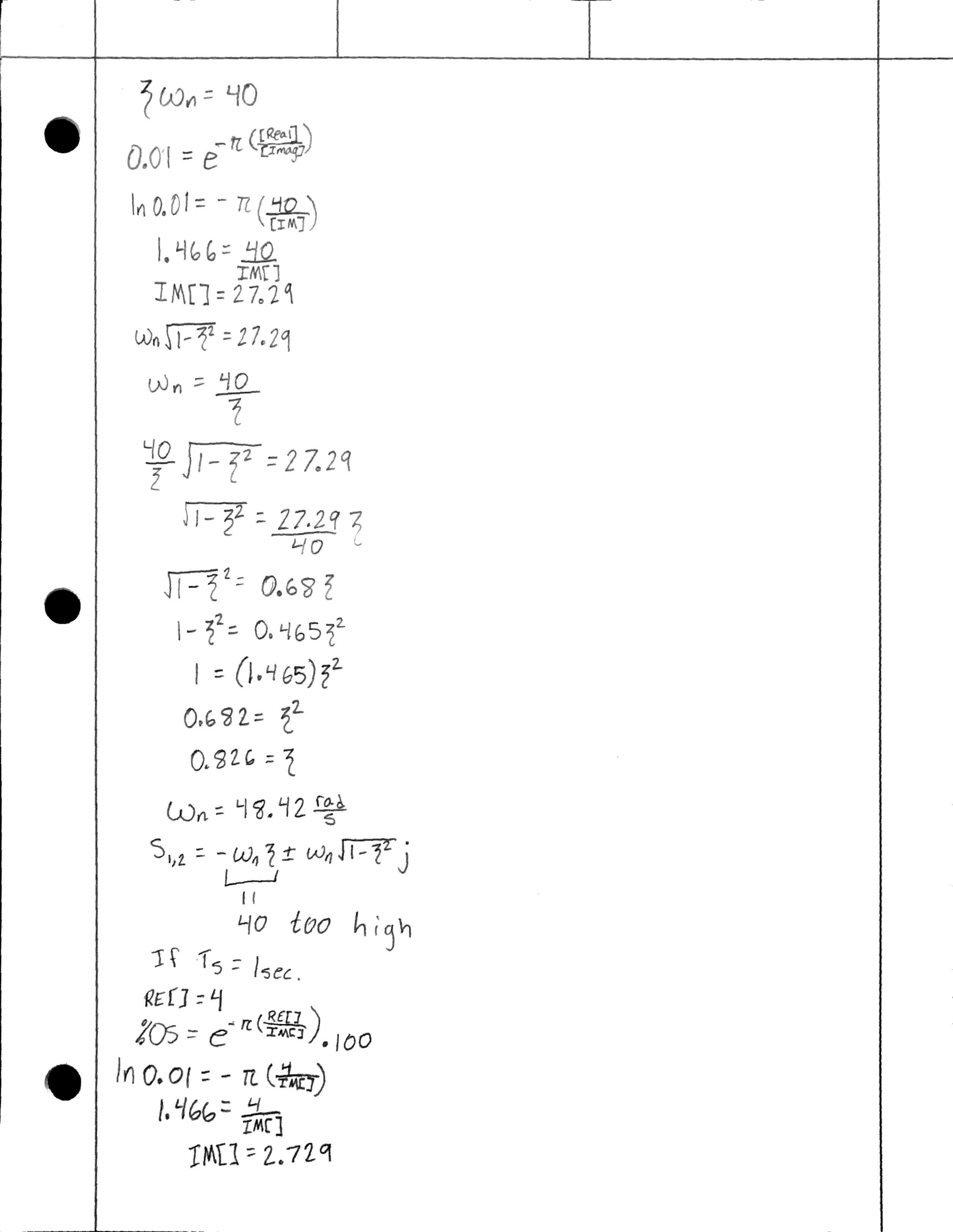
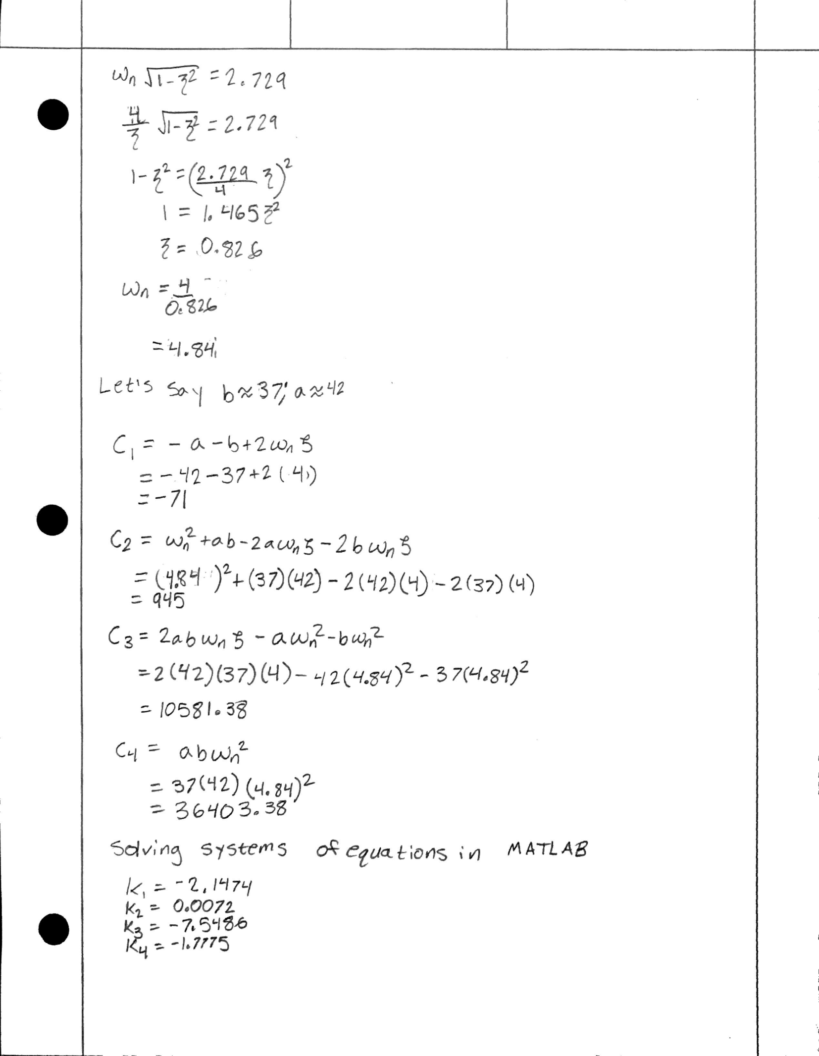
Once acquired, measured values are used to find the motor torques required to balance the ball. Torques are determined by multiplying the measured values by calculated motor gains. The torques for each motor are then converted to a duty cycle value which is used to move the motors appropriately. The calculations for the gains can be found in Gain Calculations.
More detail on the methods used: The best results we were able to achieve determined the angle and angular acceleration of the table from the encoder position. We did this by dividing the position (and speed) by 255 (the total counts in a full rotation). This poduced the the motor's location a percentage of its total rotation. By multiplying that percentage by 2pi, we determined the displacement of the motor (and in effect the platform) in radians. From there we could multiply the length of the motor arm by the sine of its angle to get the vertical displacement at the end of the rod. That displacement was also the change in height of the edge of the table because we assume that the push rod stayed vertical. From there taking the arcsine of that vertical displacement and dividing by the length from the center of the table to the edge, produced the angle of the table. The same could be done with the change in encoder position to get the change in table angle. The code then multiplies each of these results by the gain value calculated. Because our touchscreens did not work, we were unable to balance the ball on the table as we had hoped. If we were able to do so, the process would be similar to that of the angles. With the touch screen implemented, we would be able to easily tell the ball's position. By consistently interpreting values scanned by the screen, could obtain the change in position with respect to time, giving us the velocity of the ball. As touched on earlier, we could then multiply those by the gains we computed. Once complete, we could sum up all of those torques, from the angle, position, angular velocity, and velocity, multiply by the motor resistance and 100%, then divide by the power supply voltage (12V) and the torque constant (0.0138 Nm/Amp) to get the necessary duty cycle. As it is, we could only compute the duty cycle without the torques produced from the linear speed and position of the ball.
We were unable to successfully balance the ball on the platform. We attempted the problem from a number of angles with varying methods (see The Attempts).
However, we are proud to say that we did end up figuring out how to apply the gain value method that we learned in class to our project. In a classic "learn by doing" scenario we frankly didn't fully understand it unitl we tried it... multiple times. As far as the gains go, we learned that the ones we produced from hand calculations were far lower than what was required to properly contol the table. With some tuning we were able to smoothen the leveling process. We think this had to do with the friction present in the physical system being much higher than that assumed in our calculations. We shot for a settling time of 1 second and a percent overshoot of 1%. Aspirational goals give the state of our system, we unsuprisingly were incapable of achieving them. The greatest improvements we could make to the system to achieve the desired response would include tightening the belts and reducing the friction between the belts and their gaurds.
Original Gains: K = [-2.1474, 0.0072, -7.5486, -1.7775]
Tuned Gains: K = [NotApplicable, 1.3, NotApplicable, 8.2]
We made a number of attempts to create a fully indtegrated system respondant to a touch panel. The following are the source files to a number of such attempts. It is recommended to view them in the order they were attempted as the doxygen descriptions each attempt references previous versions. The fifth file is a cleaner version of Attempt 3 that offers greater modularity and can more easily be run on other balancing systems. The following video captures one of the earlier balancing attempts: https://youtu.be/0fpSM2Fekm0
Although unsuccessful in fully achieving our goal by the project deadline, we made significant progress overall and gained a much deeper understanding of Micropython, motor/sensor interfacing, modeling dynamic systems, and designing controllers. Our biggest take away: this sh*t is time consuming and hard. Nevertheless it is fascinating and endlessly engaging, hence why we keep coming back for more.
A major hurtle we encountered which set us behind significantly was not having reliable readings from the touch panel. Both my partner and I had issues. We each used the code we independently developed in Lab07. Although we were both found success reading values previously, we did not have the same success in this lab. Regularly the touch panel would incorrectly report being touched and/or provided bogus readings. We believe the issued stemmed from the way we attached our boards to our respective top plates. Lab07 tested the touch panel prior to adhering it to the top plate. Whether it be an error from soldering or adhesion we are unsure. A lot of time was dedicated to diagnosing and resolving the issue before we decided to focus our efforts elsewhere. Despited not being implemented, we developed code for the touch panel. It is untested, however.
On a brighter note we were successfull in balancing the platform and having it right itself when perturbed. Additionally we were able to successfully calculate the required system gains (see Gain Calculations). And we learned a lot and had fun doing it! There's not much better than that.
Reflection: If I had to restart the project from scratch, I would begin by incorporating drivers separately thus minimizing the code to debug in each iteration. Having everything included at once made it difficult to find where the bugs were hiding. That was our main error with mainWithnFault.py. Finishing this project on time was also extremely difficult given my schedule during the tail end of the quarter. Now that the quarter is over, I plan to spend Spring Break debugging and completing the project.
Calculations for the gains done mostly by hand, some parts in MATLAB
Explanation: https://youtu.be/_cNrHkeaciU
Demo 1: https://youtu.be/JoiuYJn16t4
Demo 2: https://youtu.be/0fpSM2Fekm0
Final: https://bitbucket.org/dhmorse/mechatronics_shared/src/master/Lab09/HM/
Attempts: https://bitbucket.org/dhmorse/mechatronics_shared/src/master/Lab09/Ultimately%20Futile%20Work/
This lab was completed in collaboration with Jacob Everest https://mediocre-coder.bitbucket.io/